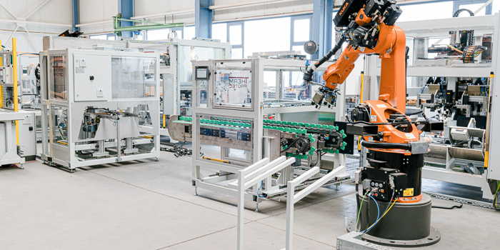
SBL | SMART BONDING LINE
Why a modular production line?
The market for vehicle stabilizers has changed significantly in recent years. On the one hand, tubular stabilizers are used instead of solid stabilizers due to today's weight requirements. On the other hand, these components are fitted into the geometric boundary conditions and integrated into the body. As a result, the mounting options have also changed and rubber bearings are glued onto the stabilizers. These are connected with special fastening clamps. At the same time, energy-intensive hot-air ovens were replaced by local inductive heating during the manufacturing process. This makes significantly more economical processes possible. In order to meet these versatile requirements, ThermProTEC has developed a modular production line concept which implements the fully automatic manufacture of stabilizers with all conceivable quality assurance systems.
Module of the production line
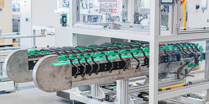
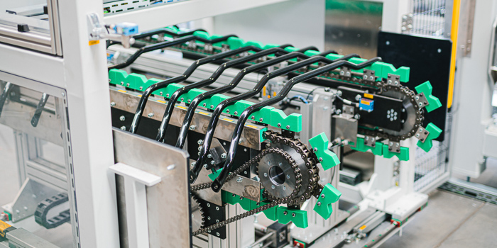
At the heart of the line is a new workpiece carrier concept with the aid of which adhesive bearings are conveyed on a accumulating roller conveyor system by loading, inductive heating and unloading. The basic components conveyor belt, fully automatic loading system, inductive heating system and unloading system are fixed components of the unit. Depending on the degree of automation required, the automatic bar feed, diameter and weight measurement, barcode application, scorching, brushing and oiling as well as the removal of safety screws can be fully automatically extended with robot systems on the loading side. On the unloading side, the fastening clamp is integrated by means of a press with automatic clamp feed as well as the subsequent quality assurance with camera systems and robot handling. The system is available for different cycle times. The shortest cycle times correspond to a capacity of 240 stabilizers per hour. Format adaptations are realized fully automatically by means of electric actuators. All quality assurance systems including Poka Yoke are possible during system design and are accepted by the automobile manufacturers. All process data and properties of the stabilizer are transferred to a database and individually assigned to each stabilizer. This guarantees traceability.
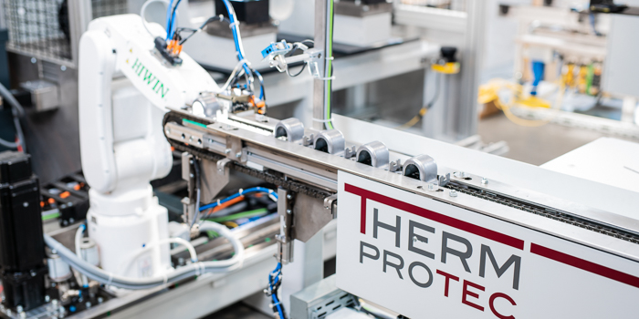
feed belt
The stabilizers are inserted into the system via the central infeed belt. The operator manually loads the belt with stabilizers. The orientation is checked by sensors. Precision measuring systems then determine the diameter and weight of each stabilizer. Part of this unit is a label printer with applicator for individual marking of the components. The component is centered and transferred to the handling robot for further safe transfer. The barcode is read and serves to identify the component.
Cleaning station
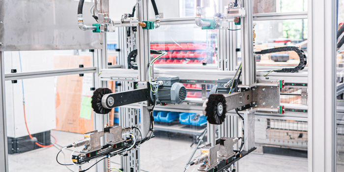
To ensure secure adhesion in the subsequent process, the adhesion point must be pre-treated. The central cleaning station serves this purpose. This is equipped with a flame treatment unit, a brush unit and an oiling station. Depending on the application, the individual work steps or a combination of these steps can be carried out. The correct execution is recorded in a database.
Charging station
The positioning of the stabilizer in the tools fitted with adhesive bearings is of central importance for the quality of the component. The loading station consists of another precise alignment and angular positioning and a 3-axis loading system, which positions the stabilizer in the workpiece carriers. The adhesive bearings are also clamped in this unit with the tools in this position and released for further processing. Here the adjustment force can be adjusted specifically. The distance between the adhesive bearings is set by means of four servomotors with absolute encoders. The workpiece carriers are fixed by means of centering pins. In a manual version, an additional barcode query can also be integrated here.
Inductive heating station
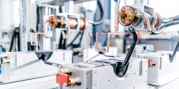 Our specially developed induction system (SIU - SMART INDUCTION UNIT) enables thermal bonding in just a few seconds. Heating takes place only locally in the area of the adhesive bearings and is therefore extremely energy-efficient. One or two induction stations are integrated into the process depending on the desired cycle time and geometry of the adhesive bearing. Quality assurance is carried out by determining the temperature of the adhesive bearing points with pyrometers and measuring the energy actually required. The reheating time is decisive for the final adhesion quality. This is ensured by the clocking of the further course of the belt.
Clamp feeding
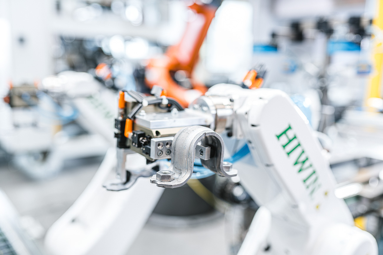
An optional clamp feeding belt with one to two handling robots is available for automatic clamp feeding and thus also for reducing the cycle time. After camera monitoring, these robots remove the clamps from a conveyor belt and automatically load the pressing tools with them. A simple conveyor belt is sufficient for one-piece clamps. Two- or four-piece clamps are fed with a double conveyor belt. The feeding of the clamps as well as the loading of the clamp crimp nuts can also take place automatically. A camera-supported "Pick and Place" system is used for the clamps.
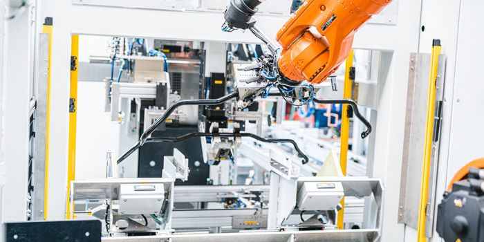
Press
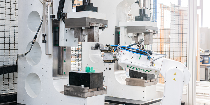 The clamps are applied to the stabilizer with a hydraulic/pneumatic press. The pressing force is up to 25 t per side and enables the application of one-, two- or four-part clamps. The clamp spacing is adjusted by means of an electric actuator with absolute encoders. A tool change system secured with Poka Yoke is used to integrate different types of clamps. Additional sensors on the tools ensure the quality of the pressing. A special variant of this enables omega pressing, in which the clamps are pulled on and compressed to a defined final dimension.
GU system
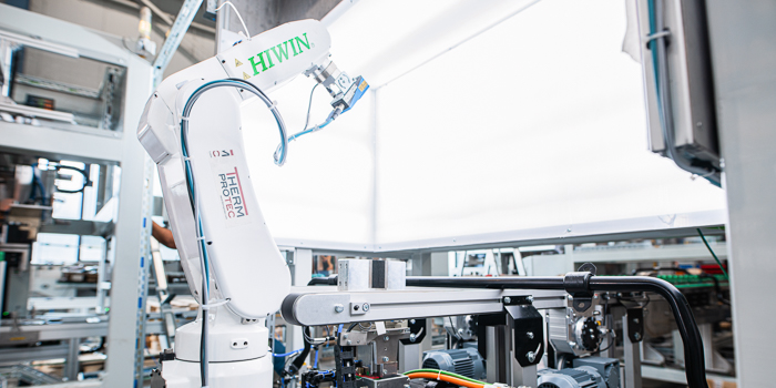
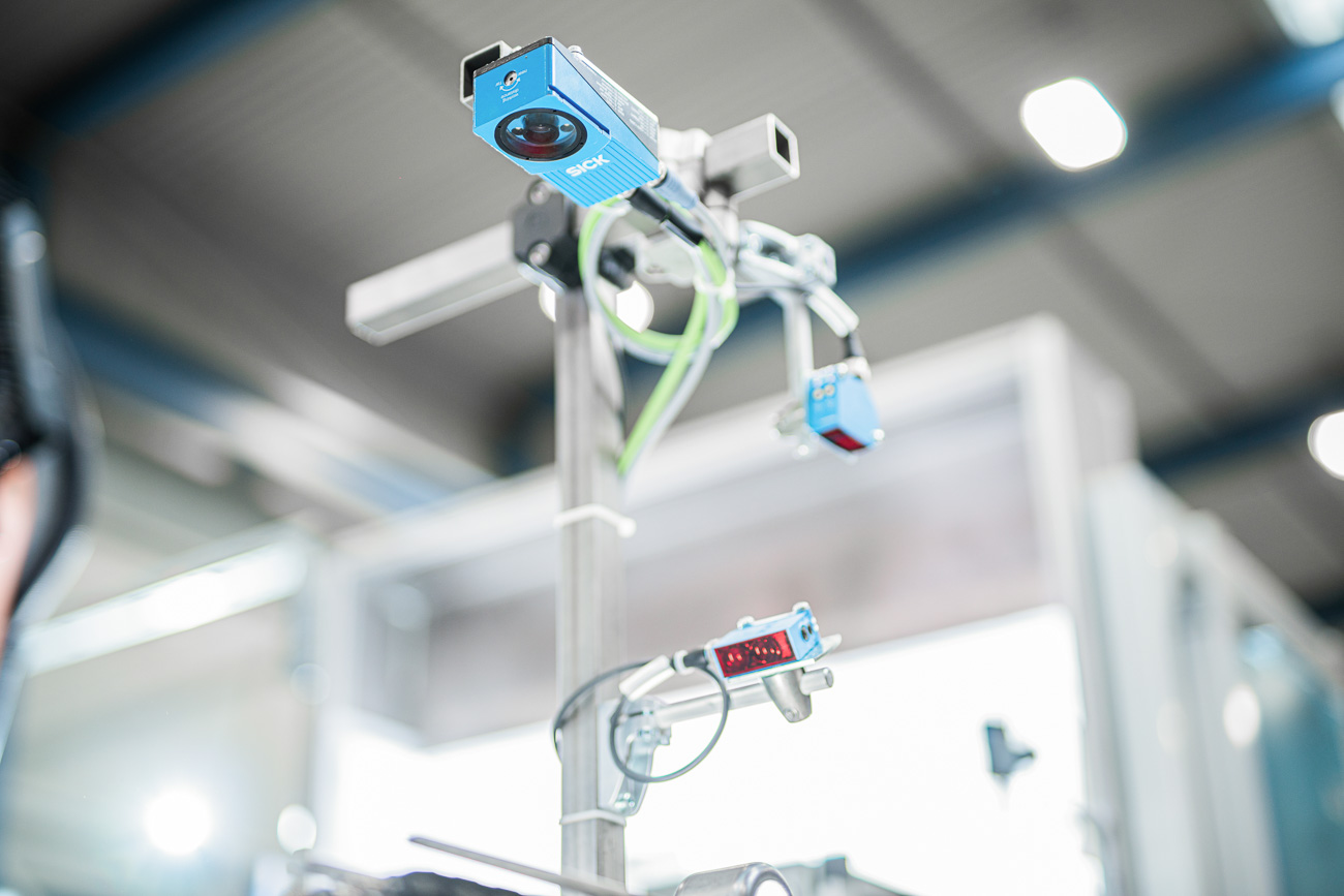
Optionally, the geometry of the component at the end of the process chain can be measured automatically, thus reducing the risk of missing parts. For this purpose, a handling robot feeds the finished stabilizer to an optical measuring system. A pneumatic gripper on a height-adjustable servo axis positions the stabilizer in front of two stationary cameras. Another robot with a smartcam additionally measures the fixing points of the clamp and the alignment of the stabilizer in the clamp. After this process, the stabilizer is fed to an outfeed belt and thus transported out of the safe cell for removal. This data is also fed into the central database and stored.
Discharge station
The unloading station is constructed analogously to the loading station. The workpiece carriers are opened and fed with the 3-axis loading portal to an adhesive bearing distance measurement. The distance is determined using two smartcams and documented in a database. After this process, the stabilizers are deposited in a station or on a transfer belt. Light barriers secure the area in case of manual handling of the system. The format setting is also carried out here with integrated servomotors with absolute encoders.
From process development to turnkey production facilities. We develop innovative solutions in the field of thermal process technology. From the automotive industry to mining, you are in good hands with us.
Useful links
Contact